
Allowable Nozzle Loads
You may have seen, far too often, a back and forth between piping engineers and equipment engineers on pressure vessel allowable nozzle loads. This results in a noticeable schedule impact and therefore a cost impact in engineering hours. Both sides may have a point…
As the piping engineer, these loads are absolutely required to have an accurate stress analysis. In accordance with ASME BPVC Section VIII-I UG-22(c), it is required that external loads be considered for pressure vessels. This section of the code goes on to list the types of external stresses (seismic, weight, piping, etc.).
As the equipment engineer, you must consider internal / external pressure, displacement stresses of the vessel (thermal expansion / contraction), seismic loads, transportation loads, and the list continues on. Therefore, as a conservative approach, the equipment engineer may set these allowable nozzle loads close to 0 with the idea that the piping engineer can compensate with supporting the pipe correctly.
The low nozzle allowable loads cause this back and forth which ultimately costs time and money. So how do we fix this disconnect in the design process?
One way we can prevent this back and forth between piping and mechanical disciplines is to design the equipment and piping simultaneously.
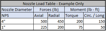
Goodrich Engineering utilizes industry leading software that checks piping nozzle loads using WRC 537 (supersedes WRC 107). It is often more accurate and easier to use code software that implements WRC 537 compared to an FEA software. The code software also allows you to generate automatically allowable nozzle loads within your nozzle schedule:
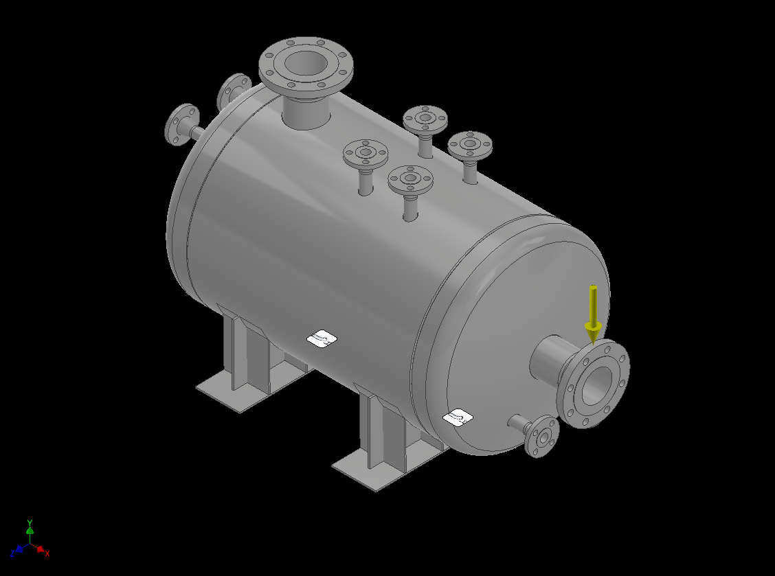
Radial Load Case - FEA shown as an example only
Designing both the pipe and equipment in tandem helps create a comprehensive design that is compliant with ASME B31.3 and ASME BPVC Section VIII Div. 1 UG-22(c) (and UG-44). This approach reduces the cost and schedule impact of the piping and equipment design phase.